Thursday, December 31, 2009

Ardubot Arduino

Yeah, programming time!

First step is to download and get the software up and running for the Arduino.  I didn't have any problems, but that might be because I had some other serial and avr stuff already installed.  Some people I believe had do download java or some such other things.

Step two is to hook up the Arduino so that the computer can see it.  Under the tools drop down menu you will need to select 'board' and select which board you are using.  Then you will select 'serial' (also under the tools menu) and select where your board is attached.  There are ways to find out which port your board is attached to but trial and error works too.

Next we are going to start typing, I know I could give you a file to download, but I think you learn more if you type it (although you will probably just copy and paste anyway).  So here is the code


char MLR = 9;  //Left Motor Reverse
char MLF = 6;  //Left Motor Forward
char MRR = 5;  //Right Motor Reverse
char MRF = 3;  //Right Motor Forward

void setup(){
pinMode(MLF, OUTPUT);
pinMode(MLR, OUTPUT);
pinMode(MRF, OUTPUT);
pinMode(MRR, OUTPUT);
}


void loop(){
digitalWrite(MLF, HIGH);
digitalWrite(MRF, HIGH);
delay(1000);
digitalWrite(MLR, HIGH);
digitalWrite(MRR, HIGH);

delay(1000);
}


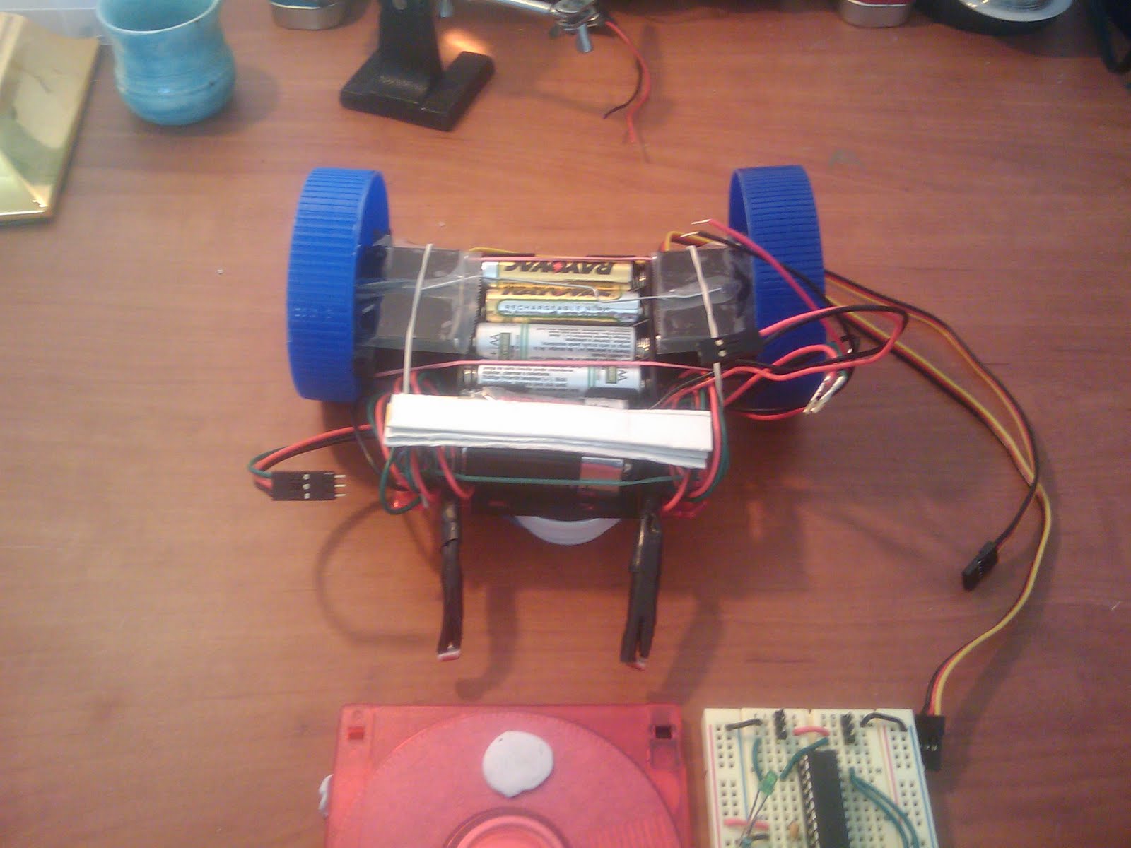
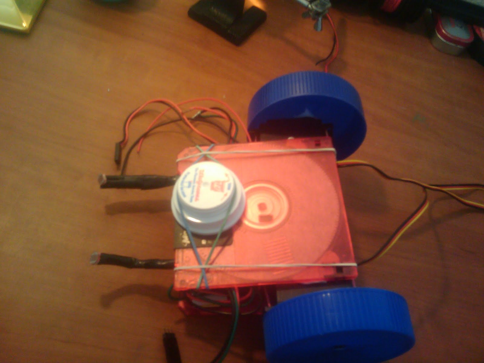
When its all typed you are going to select the left most icon on top, the one that looks like a play button.  This will compile or verify your program .  At this point make sure your Arduino board it attached to your pcb board. Then select the second to last button (a right arrow) this should upload the program to your Arduino.  After a second or two the Arduino will restart and you should see/hear your motors going.  Now is a good time to unplug the Arduino, once the Arduino is off you can add the wheels.  Don't put the wheel by the USB port all the way on, you still need the USB cable at this point for power.  So try it, see what you've got, and have fun playing with the code

Monday, December 7, 2009

Ardubot Solder

In this step you will need the PCP board, the headers, the power switch, the H-bridge (the IC chip) and your soldering stuff

1.  Break the headers so you have 2 pieces of 6, 2 pieces of 8 and 3 pieces of 2
2.  Solder the pieces of 6 and 8 onto the board in the holes that are labeld
3.  Solder 1 of  the 2 pin pieces in the unlabeled holes next to where the power switch goes
4.  Solder the powerswitch in
5.  Solder the H-bridge in

The silk screening will be on the bottom of your robot.
All pins should be placed so that the smaller end goes through the board, and the longer end is sticking up
The H-bridge goes on the bottom of the board (match up the notch on the board and the chip)

6. Solder the other 2 pin pieces next to the H-bridge facing down
7. Screw the motors onto the bottom of the board with the brakets (brakets are keyed).  Don't attach wheels yet
8. Bend the 2 pin pieces next to the motors so they are near the contacts on the motors
9. Solder the 2 pin pieces to the motors
10. Turn off the soldering iron we are all done soldering (except for the wireless part which comes way later)


Check out sparkfun's tutorial for pictures on correct placement here

Ardubot Parts

The Bot
Arduino - the brains of the robot $29.95
Ardubot PCB Board - the base of the robot $14.99
Wheels - 2 wheels $6.95
Caster - 1 caster $2.95
Motors - need 2 motors $15.95 each
Motor Brackets - set of 2 $4.95
H-bridge motor driver - needed to run the motors $2.35
Power switch - turns battery power on/off $1.50
Headers - their tutorial says 2 but I only used 1 $2.50
Battery Holder - regulated battery holder, 5V $10.95

Wireless Stuff
xbee - this is the wireless module, you will need 2 $22.95each
xbee explorer - this connects your xbee to your computer $24.95
xbee explorer regulated - the connects your xbee to your bot $9.95

Other stuff
computer with usb
usb a-b cable
usb a-mini b cable
soldering iron/ solder
wire
wirecutters/ wirestrippers
screwdriver

Look, I have an Ardubot

So sparkfun was suppose to have a robot class and competition this past weekend, they ended up getting canceled and morphed into more of a workshop.  Lucky for me I got to go.  In about 4 hours I had a arduino bot up and running by remote control on my netbook.  So, I'm going to go through and do another tutorial and once again it might take me a while to get through it...

Ardubot Parts
Ardubot Solder
Ardubot Arduino
Ardubot Battery
Ardubot Wireless

Sunday, October 25, 2009

Thursday, July 16, 2009

$150 robot - Build the chassis

Part 8 - Build the chassis

I built my chassis out of 2 floppy disks, and 2 peanut butter lids for wheels. The floppy's are a bit small but I was able to fit the batteries and servos between them and the bread board on top. The PB lids worked pretty well for wheels, I just poked a tiny hole in the center and then screwed them on to the servos. When I did my first draft everything was held together with poster putty and rubberbands. This worked well for everything but the servos, they need to be secure and not come off, so I ended up using a hot glue gun and attaching them securly to the bottom floppy. The top floppy still uses poster putty which allows me easy access to the batteries.

You will also need to add a caster to the front, basically it just slides around, I rubber banded a rx vial lid to the bottom and it works well on floors (not so well on carpet). Basically making a chassis is up to you, you can salvage parts from the house, the garbage, the kitchen or you can buy them (check out this site for chassis and chassis kits) which might be a bit expensive

There are a couple of downsides to this design
1. Exposure: the circuit and everything else is completely exposed, not good for running into or off things. The robot book I got put all the parts in a sandwich container, much less exposed
2. Wheels: Peanut Butter lids are cheap but you have to make sure your hole is centered (although mine had little dimples in the center) and they're not that sturdy. Check out lego wheels or such is you want better wheels and/or better traction.

Saturday, May 23, 2009

$150 Robot - Build the Circuit

Part 7 - Build the circuit

Some people say breadboards, some people say solder your board. I think breadboards are fine unless you want you robot to be permanent, but if you might ever want to recycle parts stick with the breadboard. That's why we chose small cheap boards. Eitherway you will want to make your first draft on the breadboard.

Here's the schematic that's used for the $50 robot (which is really what we're building)

Basically we need:
power - input, voltage regulator with capacitor, led, power switch (optional)
sensor inputs - 3 pin headers that have vcc, gnd, and pin to the microcontroller (pins 27,28)
servo inputs - 3 pin headers that have vcc, gnd, and pin to the microcontroller (pins 2,3)
microcontoller - use the ic socket (especially if you are soldering)
we don't need the program header because we won't be programming the chip on this board

Thursday, May 21, 2009

$150 Robot - Sensors

Part 6 - Make the sensors

Now we make the light sensors, the society of robots has already done the work of writing a tutorial so here we go...
http://www.societyofrobots.com/schematics_photoresistor.shtml

crimping really does make things nicer

Note: I made my cables over a foot long which I'm sure is useful in some applications, I really only needed about 3" meaning I had lots of wire to hide out of the way. In fact it might not hurt to make a set of long wired ones and a set of short wires. Or a set of short wires and an extention cable...

$150 Robot - Servos

Part 5 - Servos
Servos are a type of motor, sure you could probably use a regular motor but servos seem to be very popular with robot people. There is one problem though... servos are manufacture to move 180degrees meaning your robot isn't going to go very far! So we have to modify it a bit...
$50 robot tutorial
A picture tutorial
between these 2 tutorials you should be able to modify your servo. Basically there are 2 things that need to be done. The first is modifing the servo so that it always thinks it at the zero position. The second is clipping off a piece of plastic so that it can go 360degrees

For this little project you will need:
screwdriver
superglue
sharp knife (sharp wire cutters might work)
maybe a file, depending on how well your cutting turned out
your programming board, and a few wires to connect the servo

Saturday, May 16, 2009

$150 Robot - Blinking Light

Part 4 - Blinking Light
Go to http://www.sparkfun.com/commerce/tutorial_info.php?tutorials_id=93
Solder a resistor to an LED so that you can directly plug it in
Put LED between GND and any of the outputs (8 and 9 works)
Download the zip file
Open Programmer's Notepad
Follow directions for running make file
Follow directions for programming
Pray

You should now have a blinking light (this is the "Hello World" of the electronics world).

If its not working:
1. check all your connections
2. make sure all the appropriate power leds are on (if not its a hint of where something is wrong)
3. make sure if you are telling it which programmer you are using (usbtiny)
4. make sure you have told it the correct chip in all the correct places
5. take a break, come back, check 1-4 again (sometimes your eyes and brain need a rest)

Friday, May 15, 2009

$150 Robot - Programming chip

Part 3 - Getting programs on the chip
Download drivers http://www.ladyada.net/make/usbtinyisp/download.html
Unzip drivers
Plug in USBtinyISP
Follow directions here: http://www.ladyada.net/make/usbtinyisp/drivers.html
Download winavr http://www.ladyada.net/make/usbtinyisp/avrdude.html
Install winavr http://www.ladyada.net/make/usbtinyisp/avrdude.html
Got to run and type "cmd"
Run:
avrdude -c usbtiny -p attiny2313 -U flash:w:test_leds.hex
Don't worry, it won't do anything, just making sure avrdude can find the USBtiny

$150 Robot - Build USBtiny

Part 2 - Build USBtiny programmer
Well now you are an expert at soldering (while the board is useful so is the soldering practice).  Now we build our programmer.  The website tells you everything you need to know.  Go ahead and put the jumper on.

Thursday, May 14, 2009

$150 robot - Programming board

Part 1 - Building your programming board

This is the board we are going to program our chip on.  We are going to need a place to put the chip, and interface to our programming cable, we will also need power to our board, and an on/off switch is good too, and an led to let us know things are on)


-Learn about power / LEDs and resistors- sparkfun
-Learn how to solder (try google)

-Figure out what chip you are using, how may pins and the pinout evilmadscientist (programming headers), avrfreaks (chips)
-Things you need - Power, switch, led, dip socket, 6 pin/10 pin programmer, 9v bat/wall plug
-Figure out what other things you might want on the board (led tester, breadboard pwr output, more than 1 chip...)
-Layout your PC board, get your needed parts, wanted parts and start sticking things in holesDon't forget the power buses (connect a bunch of holes -if its not already done- and connect it to your power, connect another set to ground) this way you have easy access to all those wires you will have to connect to vcc and ground..  Mark pin 1 of chip and 6/10 programmer on board (both sides) so you don't get confused.  Once you've figured out how you want things arranged you can start soldering (you might want to take a picture first so you remember where things go).
-Solder everything in place. Use your multimeter to make sure you have good connections

Some things I did/learned:
1. USBtiny provides power to the board, but add a 9v battery adapter to make your board portable.
2. Make sure you have atleast 1 extra row beside your dip socket, once your chip is in these let you access each pin with a wire. If you need more than 1 or 2 holes just attach that wire to a small breadboard and go to town
3. You probably only need either the 6 pin or the 10 pin adapter since the USBtiny has outputs for both, but I had room and this way I can use the extra headers to test since they are connected.
4. Switch, mostly important for the battery
5. LEDs let you know if there's power and where its coming from. My programmer doesn't have a tight fit so the LEDs let me know when my cable is loose (which it usually is) and when I have a good connection
6. I didn't get around to adding a socket for a 8pin chip but I left room for it. 8 pin chips are alot smaller (duh) but have basically the same functionality just less input/outputs. I can see this being useful.
7. LED tester, don't like trying to figure out which end is positive and which is negative. I just hooked up 2 female headers and a resistor and marked which is which, so I can just touch the LED to the tester and if it light up I know it works and which end is which.
8. Get a couple of LEDs and solder a resister to the negative end (it doesn't matter which end, just be consistent) now you have plug and play LEDs , which are good for tons of things, stick them anywhere to see if you have voltage, add lights for fun...
9. Find a couple of standoffs, screw them into the corners of you board so it stands up nicely
10. If you have wires coming off (battery in, pwr out, etc) add a bit of superglue to them at the edge of the board to help prevent them from being ripped off, superglue is much stronger than solder!

$150 robot - Parts

Tools
Breadboard $2.95 elexp.com (B)
PC Board $0.90 elexp.com
Wire $6.95 elexp.com
Wire Cutter/ Strippers/ Pliers $17.95 elexp.com (includes solder stuff)
Helping Hands $3.95 elexp.com
Multimeter $10.95 elexp.com
Programmer $22 (you have to solder it together) adafruit (sparkfun has one pre-build, don't forget a cable $14.95+$1.95)
9V Battery Holder(x4) elexp.com $0.25
$66.65

Components

Resistors $6.75 elexp.com (365 pieces) - you will need atleast 2x1.62kOhms and 1 340 Ohm for each LED (if the values aren't exact that's ok)
Capacitor $13.95 elexp.com (60 pieces) you will need atleast 1 0.1uF and 2x220uF (if the values aren't exact that's ok)
Voltage Regulator 5V-1A $0.35 elexp.com x2
IC Socket-28 pin$0.22 elexp.com x2
AVR Mega 8 (28 pin DIP) $3.66 digikey
Headers $0.75 elexp.com
Switch $0.73 digikey
LEDs $0.12-$0.16 A or B any color, get about 10 elexp.com
$28.18

Total: $94.83
(you might be able to get some parts a bit cheaper at other places, but I tried limiting the number of sites to reduce shipping costs)

Other Parts (some of these should be in the components section but I forgot to put them there)
Motors, servos (I used Hitec HS-311 servo from servocity.com $8.99 each or $10.95 at elexp.com)
chassis material (I used 2 old 3.5" floppy disks)
9V Battery (I got 2 rechargables and a charger for about $8 at allelectonics.com)
Wheels - I used 2 peanut butter lids
Hobby Knife/ Cutter/ Something sharp
photo cells$0.75 elexp.com x2
Female Headers elexp.com
Battery holder (4xAA) elexp.com

Yes I know we are under $150 but once you add in shipping, maybe a few of the optional things, a few extras of the basic items (so you don't have to pay $7 S/H next week for a $0.35 item) maybe a few upgrades, some storage containers, etc you should be at around $150

Optional

Crimping stuff - make nice ends to you input/outputs crimper tool (I used pliers, but they aren't the best), pins, housing (2 pin all the way up to 20s)
Bigger breadboard $8.50 (F) elexp.com (B) for small stuff
Soldering Iron/ Stand/ Solder (this is included in the kit in the tools section, but if you already have tools and just need an iron) $4.95 elexp.com
Better took kit (includes box) $34.75 elexp.com
8 pin IC socket - we are using a chip with 28 pins, but you might in the future want to use the 8 pin chip, you can wire the 8 pin socket to your programming board for future use. $0.10 elexp.com
Bunch of parts (if you want more than the assortment listed this pack has just about everything) $48.95 elexp.com - you would still need 28 pin socket, voltage regulator, headers, pwr in
LED kit $12.95 elexp.com
Bigger or smaller AVR chip
16MHz Crystal (not needed for this project, but needed if you want to use the chip at its fastest speed for other things)

One day soon, I'll add a list of parts you will need to do all the tutorials at sparkfun so you can order them if you want

Lots to talk about

When my $50 robot is up and running at about $200 but I've learned a lot. First things first. Learn what you're doing. Makes sense huh, well I went to a site, bought parts, found I needed different parts, bough different parts, paid too much, bought more parts... and I still didn't have anything to show for it except a bunch of parts. So I'm writing a $150 robot tutorial. I know $150 sounds like a lot, but I'm not assuming you have a soldering iron, wire, wire strippers, multimeter etc. These are the only things I'm assuming you have:

Batteries
Junk
Super Glue
Scissors
Electricity
Light to see with (you might want a brighter light, flashlight, etc)
Computer with a USB port (this can be done with linux, but the tutorial is done with windows)

Thursday, April 2, 2009

Robot book

Well I got my robot book in an starting reading, its very basic which might be a good thing. It doesn't assume you know anything, and even if you've picked up some of the stuff, having it neatly layed out for you can be nice, and often it will point out things you might have missed. Well its a new enough book that it actually has a list of websites to get parts. Here are some (as much for your reference as mine):

Digikey
Allelectronics
Jameco
Electronix Express
Electronic Goldmine
Mouse Electronics

Tuesday, March 24, 2009

Computers

One thing you do need when building robots is a computer, besides them be useful for, well for everything, you need them to program the microcontrollers. These I believe can be programed in anything from BASIC to C. Then of course compiled and downloaded.

So I figured I'm build a spare computer that only has be be able to allow me to program (and some web surfing) and keep that at my robot workstation. I've got a spare flat screen monitor that I use for LAN parties (yes, I'm that big of a geek) and enough spare computer parts to build a spare machine. Well the problem with using a bunch of old parts is that some of them work and some of them don't. I've spent the last couple of days trying different combinations of parts trying to get a computer up and running. Well next I have to get an OS on and get it up and running so I can program my microcontroller, to set my servo, so I can modify my servo, so I can build my chassis...

Friday, March 20, 2009

Wire

So my $50 robot tutorial assumes you already have wire to connect your circuits. I didn't but finding wire isn't really that hard. Knowing how to find cheap wire online with all the options on the other had. I had gotten some wire from radio shack, 3 rolls 25' each red, black, and green for about $7-$8, but I keep going through it, I'm trying to figure out how to get more wire, more colors and not cost so much. Just make sure you get solid and not stranded, stranded doesn't stay together well enough to get in little holes. From what I can tell 22 guage is about standard size. After looking a while I found a site that has 100' rolls for $5.95 (and just about anything else you can think of), although I make no promises about the quality of the site.

http://www.allelectronics.com/make-a-store/category/825450/Wire-/-Cable/Hook-Up-100-Rolls-/1.html
Oops, it looks like his is stranded wire :(

But electronicx express does have 25' rolls for $1.05 (100' rolls are $5)

Stuffs in!

Well I got all my stuff in today (except for the book from amazon, but I don't need that for this project). Its amazing how quickly you can loose track of time when you're playing, its now after 1am and I should probably go to bed soon. This little $50 robot is harder than it seems. A couple of things I noticed:

Servos - they need to be modified if you want them to go around in a circle (not just 180 degrees), but this requires programing your chip to get the potentiometer to the right spot, anyway, at that point you might as well build your circuit board.

Circuit Board - All the pictures are great if you are using a pcp board and soldering everything, but if you are using a bread board it doesn't work, you can't just put things next to each other and not connect them. This wasn't too big of a problem until I got to the header to attach the programmer, the header is 10 pins in a 2x5 configuration. Unfortunately, nowhere on my bread board can I put a 2x5 pin configuration with each pin independent. This caused me to have to do some problem solving.

Cable - Since the programing cable is about 6" and needs to be connected to the computer I figured I'd just make a "cable" that allowed me to configure my pins on my breadboard how ever I needed. We'll see how it works.

Well I basically got my circuit, built, I've got my pin outs for my cable and just need to add the wires, but that's for another day...

Sunday, March 15, 2009

Who wants to hear about robots....

Probably no one, but you are here so maybe not. I decided robots were a fun way to get back into playing with electronics, but I didn't know where to start. So, I did what I do any time I am in any way confused or don't know an answer, I go to google. Over the past couple of months I bought an ordered books, and supplies, but I've been busy so I haven't gotten started. Anyway, here are a few places to start:

This is a page that walks you through building a robot for under $50. $50 might sound like a lot, but some of the things like the programmable chip and the cable to program said chip are probably about half the cost and reusable.


I also went to amazon and found the robot book with the best reviews and this is what I came up with: Robot Building for Beginners by David Cook (about $20)